
Working with multiple terrain layers
Load several DEMs, show, hide, rename, reorder and fade them, understand when layers are aligned, and compare two surveys of the same area.
You will learn
- Manage several layers in one workspace.
- Understand alignment by coordinate system.
- Compute the elevation difference between two DEMs.
Prerequisites
Data for this tutorial
Sample valley DEM (synthetic) Download orbis3d-sample-valley.tif
- Format
- GeoTIFF, 1 band, Float32, Deflate, tiled
- CRS
- EPSG:32643 (WGS 84 / UTM zone 43N)
- Content
- Elevations 419.5 to 1452.5 m; NoData -9999 in the south-west corner
- In Orbis3D
- Data panel ▸ Sample data ▸ Sample valley DEM (synthetic) ▸ Load
- Licence
- Synthetic, CC0 1.0
Sample valley, later survey (synthetic) Download orbis3d-sample-valley-2026.tif
- Format
- GeoTIFF, 1 band, Float32, Deflate, tiled
- CRS
- EPSG:32643 (WGS 84 / UTM zone 43N)
- Content
- Elevations 419.5 to 1452.5 m; quarry about 28 m deep, landslide deposit about 11 m thick
- In Orbis3D
- Data panel ▸ Sample data ▸ Sample valley, later survey (synthetic) ▸ Load
- Licence
- Synthetic, CC0 1.0
Synthetic samples are CC0 1.0; the SRTM sample is public domain. About the datasets
The task
The same valley was surveyed twice. Between the surveys a quarry was dug and a landslide moved material downslope. You load both DEMs and compute where the ground went down or up.
Steps
- Load Sample valley DEM and then Sample valley, later survey from Data ▸ Sample data. Both appear in the Layers panel; the newest is at the top.
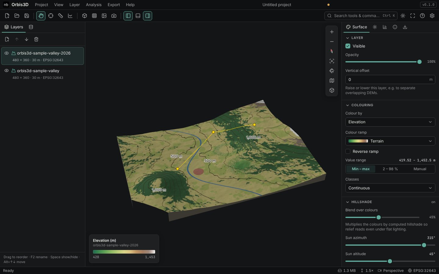
- Manage the layers:
- Show or hide a layer with its eye button or Space.
- Rename it by double-clicking its name or pressing F2.
- Reorder by dragging, with the arrow buttons above the list, or Alt+↑/↓.
- Select a layer by clicking it. The Surface, Analysis, Info and Export tabs work on the selected (active) layer.
- Fade or lift a layer in Surface ▸ Layer with Opacity and Vertical offset.
- Check the alignment. Both layers use EPSG:32643, so they are placed at their true positions and overlap exactly. A layer in a different or unknown coordinate system gets a Not aligned badge and is shown beside the others, because Orbis3D does not reproject DEMs.
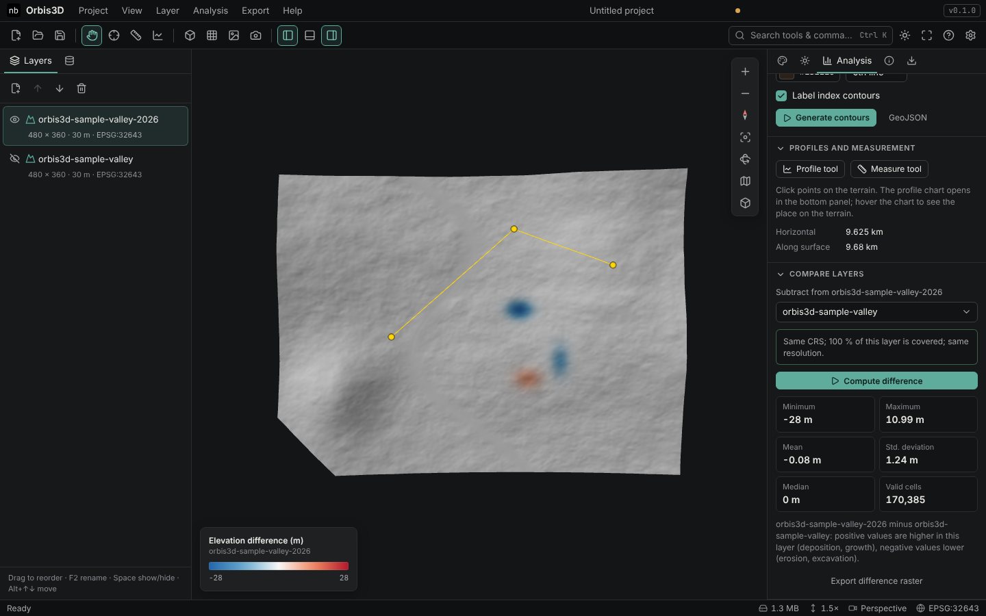
- Select orbis3d-sample-valley-2026. In Analysis ▸ Compare layers, choose orbis3d-sample-valley under Subtract from orbis3d-sample-valley-2026. The check reads "Same CRS; 100 % of this layer is covered; same resolution."
- Click Compute difference. The active layer is coloured with the difference (later minus earlier) on the Blue–white–red ramp, and the older layer is hidden so that it does not cover the result.
Expected result
- Minimum -28 m: the floor of the quarry pit.
- Maximum 10.99 m: the landslide deposit.
- Mean -0.08 m and median 0 m: most of the valley did not change.
How the difference is computed
For every cell of the active layer, Orbis3D takes the other layer's elevation at the cell centre (bilinear interpolation), converts feet to metres if the units differ, and subtracts. Cells that are NoData in either layer are NoData. Both layers must be in the same coordinate system; if their resolutions differ, the other layer is resampled to the active layer's grid, and Orbis3D tells you so.
## Common mistakes- Wrong order. The result is active layer minus selected layer. Select the later survey first to get positive values for growth.
- Different CRS. Compute difference is disabled; reproject one DEM (for example with GDAL) before loading it.